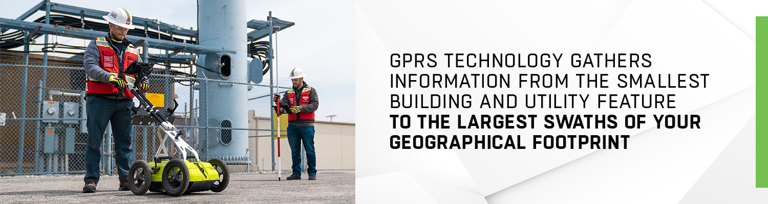
SiteMap technology is cutting-edge and uniquely able to combine site data, both above ground and subsurface. Parent company GPRS uses GIS, or a geographic information system, to combine geospatial information from the smallest building and utility feature to the largest swaths of your geographical footprint. This data is subsequently displayed in SiteMap’s user-friendly Map Viewer interface.
How does the Map Viewer work, and which features does it display?
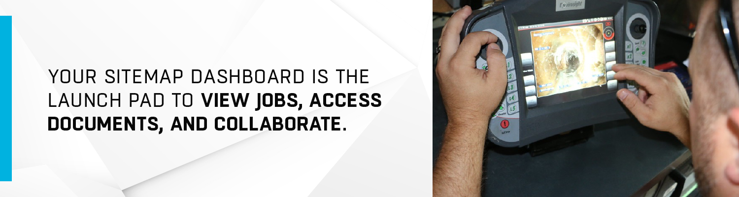
The SiteMap dashboard is the launch pad to view jobs, access documents, and collaborate with facilities and engineering colleagues. Once logged in, when you click “View Job” on your dashboard, you will automatically navigate to the Map Viewer where the individual features of your projects are visible on an adjustable map. Clicking on any feature opens a tab list that provides details on layers, tools, and descriptions of each feature. You can plot points, measure distances, calculate area, and rotate and recenter the map. You can also go directly to any saved job file directly from the Map Viewer.
SiteMap’s Map Viewer combines the features of your facilities in a novel way, presenting them cohesively as layers within the same geographic area. The available feature illustrations include:
- Drone & aerial imagery: Drone footage can provide a bird’s-eye view of how the parts of your campus are situated above ground. In a recent article, we explained how drones are reshaping the quality of geospatial data, capturing high-resolution footage from virtually any angle and storing it to the cloud. A combination of LiDAR (light detection and ranging), a barometer, and electromagnetic hyper spectral sensors can capture aerial footage and data on atmospheric conditions through a process that is much more cost-effective than satellite use.
- 3D digital spatial information: This layer is where you can digitize your building; our Mapping & Modeling Team can create 3D tours, dollhouse views, and schematic floor plans that you can view and share from the comfort of your office or mobile device. When reviewing 3D spatial information in Map Viewer, you can calculate distance and area among buildings and utilities both above and below ground, anticipating potential limitations and preventing unwelcome surprises during a construction project.
- Concrete slab components & thickness: Structural drawings of your existing underground concrete landscape are of the utmost importance. Concrete company Fricks says, “Today’s concrete floor is more than a thick layer of concrete poured onto the ground. Concrete floors have advanced technologically over the years to become a durable, load-bearing surface that resists wear and tear.” Your consolidated mapping can include data on materials within the concrete, thickness, joints, and surface treatments. Not only are these slabs the foundation of your campus, but within them lay numerous utility lines that must be considered for code compliance and future construction.
- Underground utility & pipe inspection data: Infrastructure mapping wouldn’t be complete without actual as-built specifications on sewer, gas, water, and electrical lines. While the original plans may have specified locations for each utility, the end result may be different, and your team must account for those changes to avoid safety hazards.
- Underground storage tank (UST) information: One of the more impactful aspects of any campus or property site, underground storage tanks require careful monitoring and even periodic testing to ensure that the surrounding ground is safe to inhabit. There are also numerous government-mandated spill protection requirements for USTs, and understanding their location will help to comply with regulations and prevent shifts or punctures during construction.
- Subsurface void information: Any underground holes or gaps on your property may be a risk factor when trenching, or when large vehicles or additional construction equipment occupy the space. The causes of any subsurface voids are as important to understand as the locations in which they currently exist on your property. Common causes of subsurface and concrete voids include washout, when a large amount of water washes away the supporting soil; erosion, when water or wind shifts foundations and soil over time; or animals native to your area that tunnel under buildings, walkways, and driveways.
Choosing the ideal SiteMap plan for your business
There are two levels of SiteMap services; the scope of your business, your need for consolidation, and potential future construction projects may inform which platform best suits your needs.
- SiteMap: The standard version of the system allows you to view, edit, download, and share site maps of your facilities. Additionally, we offer clear insight into 3D models of your buildings, allowing you to perform walk-throughs.
- SiteMap Plus: In addition to the above mentioned functionality, SiteMap Plus adds depth to your mapping capabilities. You can view site infrastructure through augmented reality, and use quantum GIS-based viewing, editing, and map composition.

Conclusion
Visualizing the many structural and utility elements of your facilities can be a daunting task when approaching a construction project or completing required maintenance. SiteMap’s Map Viewer demystifies that process, providing an expertly-designed depiction of how your building features are situated, relative to each other and the geography around them. The standard SiteMap program can provide information you need to get started, while SiteMap Plus offers a deeper, enterprise-level view of your campus. Contact us to help kick off your next mapping project today!